|
|
You are here: Foswiki>DaqSlowControl Web>OutdatedPages>DaqNetwork>TrbNetMonitoring (2010-02-01, BorislavMilanovic)Edit Attach
-- BorislavMilanovic - 27 Jul 2009
 The whole monitoring system has been redesigned lately to meet all the future requirements.
TrbNetRegIO is used to provide access to the monitoring facility, hence read and write signals can be used directly on the 4-th channel of the TRBnet, not interfering with other more critical low level signals.
There are 2 types of monitoring cells by now:
The whole monitoring system has been redesigned lately to meet all the future requirements.
TrbNetRegIO is used to provide access to the monitoring facility, hence read and write signals can be used directly on the 4-th channel of the TRBnet, not interfering with other more critical low level signals.
There are 2 types of monitoring cells by now:
 This figure illustrates the contents of a FIFO cell. It is possible to tagg any signal comming from the detector with a timestamp and the event-number.
There are 3 different timer domains:
This figure illustrates the contents of a FIFO cell. It is possible to tagg any signal comming from the detector with a timestamp and the event-number.
There are 3 different timer domains:
Every FIFO has following configurations:
 Due to 'trbcmd', the user can specify one single FIFO address the should be read out, and since all FPGAs on a particular sub-detector are built alike, the user receives this monitoring signal (from the FIFO) for every sub-detector node at once.
TRBnet Monitoring System
On this page, the new monitoring facility for the TrbNet will be presented. Any user may feel free to contribute to the topic, to state his/her own requirements and to extend the functionality until the desired degree of freedom has been reached. The newest version is currently beeing tested and optimized in the IKF labs (Goethe University). It is by far not the final version, as the monitoring system is intended to be extensible to fit all the future TRBnet experiments (HADES, FAIR, CBM). There are also lots of configuration possibilities open, so please let me know - what do You want/need?Requirements
Following aspects of a universal monitoring system were in the center of attention during the design phase:- Simplicity (low ressources)
- Extensibility
- Flexibility
- Real-time access and configuration
HW Architecture
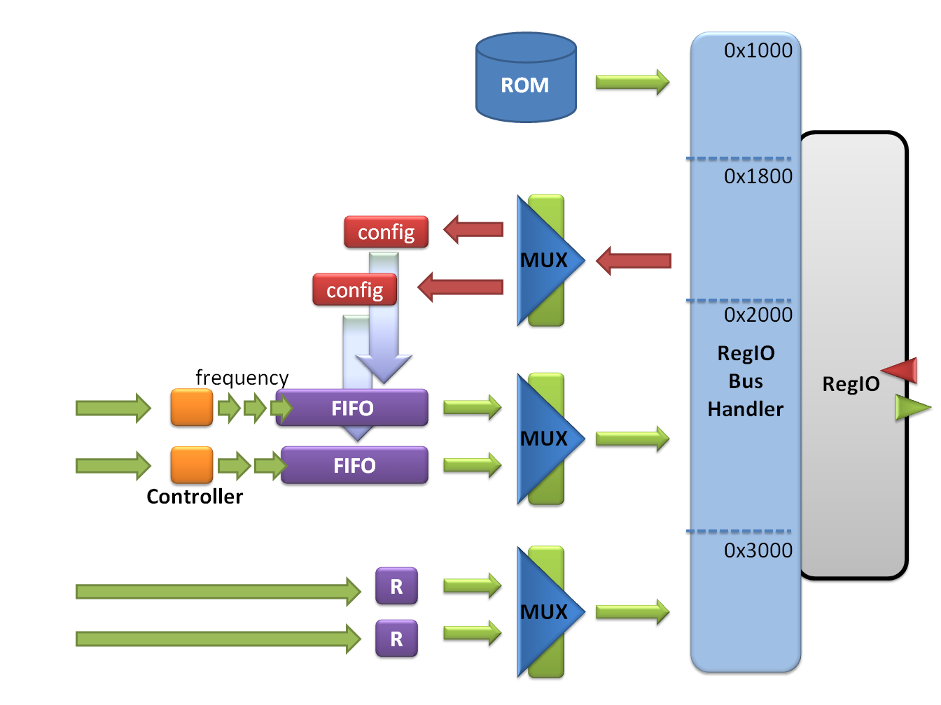
The whole monitoring system has been redesigned lately to meet all the future requirements.
TrbNetRegIO is used to provide access to the monitoring facility, hence read and write signals can be used directly on the 4-th channel of the TRBnet, not interfering with other more critical low level signals.
There are 2 types of monitoring cells by now:
- Registers (Address 3000 - 3FFF)
- FIFOs (Address 2000 - 20FF)
Data packing
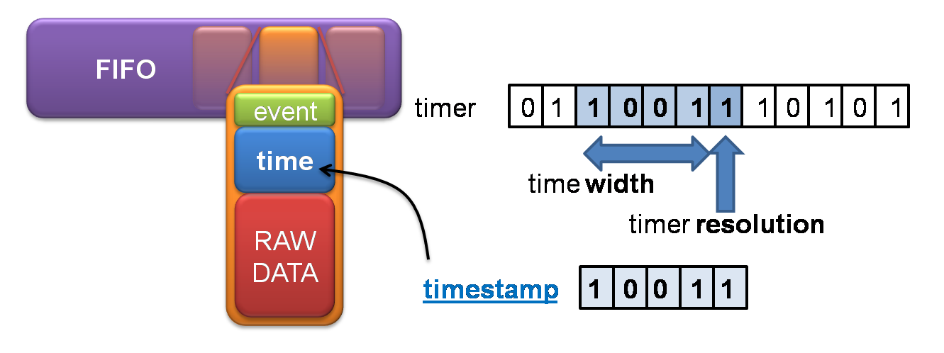
This figure illustrates the contents of a FIFO cell. It is possible to tagg any signal comming from the detector with a timestamp and the event-number.
There are 3 different timer domains:
- Global time - is the same on all TRBs
- Local time - provides higher accuracy (no sync)
- Time since last trigger
Possibilities
All FIFOs are predesigned to suit every experiment in near future. Each one can be used in a ringbuffer mode. Usually, when a FIFO is full, it discards all the new data packets trying to be written. In ringbuffer mode, it discards the oldest packet, when near full. Therefore only newest and freshest values are kept inside. When the ringbuffer mode is being used, it can be turned off. However, if a FIFO is built to not support the ringbuffer mode, it can not be turned on again (but the FIFO will spare some resources). Following FIFO sizes were specified:| Fifo list | Type |
|---|---|
| 8 x 16 | LUT |
| 8 x 32 | LUT |
| 16 x 16 | LUT |
| 16 x 32 | LUT |
| 32 x 16 | LUT |
| 32 x 32 | LUT |
| 64 x 16 | LUT |
| 64 x 32 | LUT |
| 16 x 1024 | 1 BRAM |
| 16 x 2048 | 2 BRAM |
| 16 x 4096 | 4 BRAM |
| 32 x 512 | 1 BRAM |
| 32 x 1024 | 2 BRAM |
| 32 x 2048 | 4 BRAM |
| 64 x 512 | 2 BRAM |
| 64 x 1024 | 4 BRAM |
| Config | ||||||
|---|---|---|---|---|---|---|
| .. | .. | 3 | 2 | 1 | 0 | |
| .. | .. | halt | input checking | ringbuffer mode | reset | |
Software Part
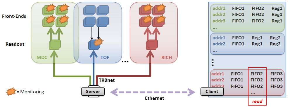
Soon, an EPICS implementation will follow. However until then, the user can control the entire monitoring procedure over a command-line interface. A client is connected via Ethernet (TCP/IP) with a server. The server is synthesized in one FPGA anywhere on the TRBnet. The client (outside the TRBnet) can read out FIFOs, Registers, ROMs and write to the config cells. The server awaits instructions and uses 'trbcmd' classes to gain access to the TRBnet over the ETRAX interface. The server is a daemon. Once started on one ETRAX chip with Linux, it listens for incomming TCP/IP instructions. The client can then first acquire all ROM information and configure itself, and afterwards this configuration (addresses, FIFOs, etc...) can be used for precise user control. The client should soon support an EPICS interface for a fine GUI control and signal visualization.
Due to 'trbcmd', the user can specify one single FIFO address the should be read out, and since all FPGAs on a particular sub-detector are built alike, the user receives this monitoring signal (from the FIFO) for every sub-detector node at once.
Discussion
Current topic - EPICS integration-- BorislavMilanovic - 31 Jul 2009 

| I | Attachment | Action | Size |
Date | Who | Comment |
|---|---|---|---|---|---|---|
| |
bigARCH.png | manage | 62 K | 2009-10-06 - 06:22 | BorislavMilanovic | The monitoring architecture (HW and SW) |
| |
DataPacket.png | manage | 89 K | 2009-07-31 - 21:05 | BorislavMilanovic | FIFO Data packet |
| |
MonitoringOverview.png | manage | 140 K | 2009-07-31 - 18:33 | BorislavMilanovic | The current monitoring setup |
Edit | Attach | Print version | History: r8 < r7 < r6 < r5 | Backlinks | View wiki text | Edit wiki text | More topic actions
Topic revision: r8 - 2010-02-01, BorislavMilanovic
Copyright © by the contributing authors. All material on this collaboration platform is the property of the contributing authors.
Ideas, requests, problems regarding Foswiki Send feedback | Imprint | Privacy Policy (in German)
Ideas, requests, problems regarding Foswiki Send feedback | Imprint | Privacy Policy (in German)