You are here: Foswiki>DaqSlowControl Web>DaqUpgrade>DaqUpgradeGbE (2009-12-31, JanMichel)Edit Attach
-- GrzegorzKorcyl - 06 May 2009
- User Logic: setup Packet Constructor, generation of raw data, assignment of headers to data portions, storage of output data, analysis of statistics
- Packet Constructor: construction and storage of output packets combined of raw data portions, user defined headers and static headers
- Packet Transmitter: transmission of packets stored by Packet Constructor and reception of input packets
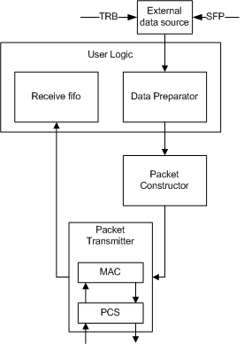 The system is designed for transmission of received data from external sources like optical links or TRB. Raw data can then be prepared in some way, for example time stamped or portioned to send each portion to a different destination. While Packet Constructor builds IPv4 packets, Data Preparator is where user can specify top level structure of his data and assign destination addresses. Prepared data is then passed to the Packet Transmitter which reads packets from Constructor and send them through the optical link. User Logic is responsible for controlling data flow between Preparator and Constructor. Its main tasks are to set up static headers, signalize Constructor about data boundaries and care about destination addresses.
Here is a detailed scheme of how Packet Constructor, Transmitter and User Logic must be connected between them. Packet Generator in place of Packet Preparator is used as data source:
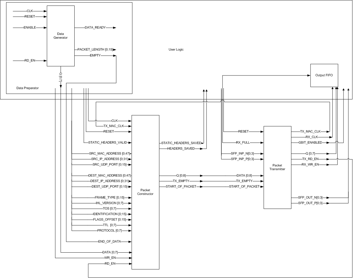 I have prepared a Data Generator, as a data source in User Logic, which uses LFSR to generate random packet lengths and random data. Previously, input data was transferred from ETRAX via TRB and addon connector directly to the Constructor.
After STATIC_HEADERS_SAVED flag is asserted by Constructor, the user can go up to prepare data for transmission. Raw data can be generated, gathered from TRB using add-on connector or gathered from other optical transceivers. Data is passed to the Constructor via 8-bit port and is saved into User Data Fifo on the other side. User, generally does not have to care about the amount of data he transfers into Constructor in case when all data has to be sent to one destination. Packet Constructor will save incoming bytes and dynamically form packets when maximal packet size (1472 B) is met, assigning the same destination addresses to all packets. When user has less data then maximal packet size, then he must assert END_OF_DATA flag when there is no more data to be transmitted. In case when user is sending large amount of data into one tination, he doesn't have to know when his data is divided into packets so it is very important that DEST_ ports have correct values during all the process of inserting data into Constructor. If destination addresses (DEST_MAC_ADDRESS, DEST_IP_ADDRESS, DEST_UDP_PORT) must be changed, the END_OF_DATA flag must be asserted as the last byte is passed to the Constructor. Then, next END_OF_DATA flag can be asserted after HEADERS_SAVED flag is asserted by Packet Constructor, which takes about 14 clock cycles.
Here is a list of all port of Packet Constructor:
Here is a list of all port of Packet Transmitter:
Before MAC reads any data, its internal configuration registers have to be configured in the right way. Settings like Gbit, promiscuous mode, some packet filtering options etc. must be set up before enabling Tx and Rx. Those registers can be read as well, and one of them indicates the state of MAC, when it is idle it means that MAC is ready to accept input data. Data is composed of headers and user data. Here is shown the packet structure: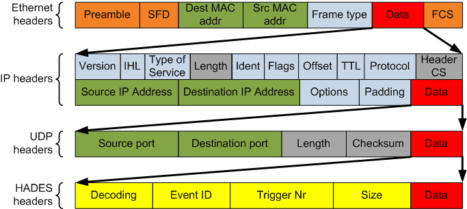 A lot of headers have constant values (the blue ones), the orange blocks are added automatically by MAC. The grey headers are added automatically by my logic and are based on input user data (the red blocks). Headers which contain addresses have to be set up by the user, this gives the possibility to send each packet the different addressee. These were the protocol headers, additionaly there are some heades of Hades DAQ system (the yellow blocks) which need to be specified while preparing data.
When user puts enough data in the fifo to form a packet, MAC starts to read data from fifo with headers. In the moment it becomes empty, MAC switches to read from user data fifo. After reading enough of bytes, MAC closes the packet by adding the checksum at its end. All the process of transmission is shown here: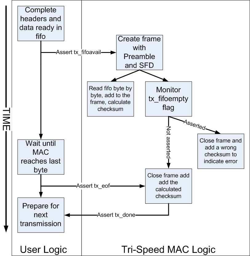
Future steps:
- Measure the speed of transmision
- Add output vector ports to the Packet Transmitter entity with statistics of outgoing packets
- Add support for Jumbo packets
- Examine the scenario when data is sent from TRB to the hub via optical fibre in 8/10 mode (right now the data from TRB is transmitted to the hub using addon connector or randomly generated on hub) and then sent using GbE
- Combine with TRBNet - Migrate to the HUB2 with Lattice ECP2M -- 06 May 2009
Overview:
Optical hub is an TRBv2 addon board which extends the main board with routing and communication features. The power of this addon is its LatticeSCM which can steer the data flow between 16 channels. Additionally we can find on this addon 2 dedicated clocks for Serdes: 125MHz for GbE which is connected to one SERDES Quad and a 100MHz for 8b/10b connected to the others.LatticeSCM communication features:
There are 4 independent Serdes Quads each containing 4 channels. The quad grouping impose using the same communication standard for all 4 channels. Thats why, one entire quad can be set in GbE mode and not only one channel. All quad configuration is done using hard IP Core FlexiPCS which generates code depending on selected settings. FlexiPCS allows us to transmit data in 8b/10b mode, to work in GbE mode we need an another IP Core which will implement MAC.Design:
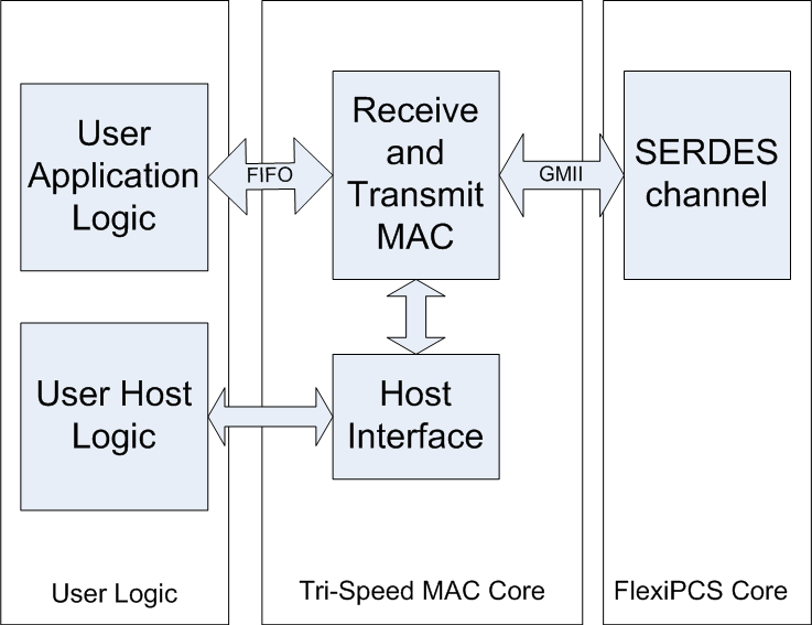
The place for Tri-Speed MAC is between the physical layer and the user logic to which MAC is interfaced through transmit and receive fifos. The communication with SERDES goes via GMII which is a set of standards describing interface between MAC and PHY. The additional thing, is that MAC has to be configured before transmitting any packets. This can be done via Host Interface and a piece of user host logic.
Test setup:
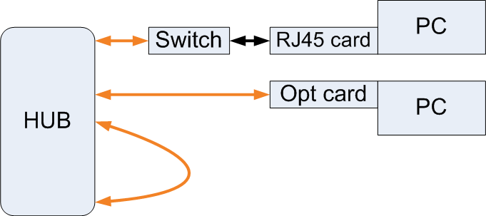
I have created a number of connections where I can test different things on hub. First one is a simple loop between two channels what means that packets are checked only on Ethernet level because they are transmitted and received by the same MAC. The second one is more advanced: the data can be sent to the PC through the switch which has a port with optical link. An alternative to this is to use a PCI card with optical link but right now we have only the switch. In the last two connections, packets must be correct on all levels: Ethernet, IP and UDP to be received on PC.
Packet transmission:
Packet transmission consists of three main elements: User Logic, Packet Constructor and Packet Transmitter.- User Logic: setup Packet Constructor, generation of raw data, assignment of headers to data portions, storage of output data, analysis of statistics
- Packet Constructor: construction and storage of output packets combined of raw data portions, user defined headers and static headers
- Packet Transmitter: transmission of packets stored by Packet Constructor and reception of input packets
 The system is designed for transmission of received data from external sources like optical links or TRB. Raw data can then be prepared in some way, for example time stamped or portioned to send each portion to a different destination. While Packet Constructor builds IPv4 packets, Data Preparator is where user can specify top level structure of his data and assign destination addresses. Prepared data is then passed to the Packet Transmitter which reads packets from Constructor and send them through the optical link. User Logic is responsible for controlling data flow between Preparator and Constructor. Its main tasks are to set up static headers, signalize Constructor about data boundaries and care about destination addresses.
Here is a detailed scheme of how Packet Constructor, Transmitter and User Logic must be connected between them. Packet Generator in place of Packet Preparator is used as data source:
 I have prepared a Data Generator, as a data source in User Logic, which uses LFSR to generate random packet lengths and random data. Previously, input data was transferred from ETRAX via TRB and addon connector directly to the Constructor.
 User Logic
This is a part of logic, in which user must supply a source of data and connects it to the Packet Constructor. Data source consists of raw data and destination addresses, so in case when packets will be sent to different destinations, user must keep track of sent data and be sure to update DEST_ ports with correct values at the right time. First thing that must be done before any packet can be transmitted is setting up static headers. To perform this the SRC_MAC_ADDRESS, SRC_IP_ADDRESS, SRC_UDP_PORT, FRAME_TYPE, IHL_VERSION, TOS, IDENTIFICATION, FLAGS_OFFSET, TTL, PROTOCOL ports of Packet Constructor must be set up and STATIC_HEADERS_VALID flag must be asserted for one clock cycle. This allows the Packet Constructor to save those values in Static Headers Ram and use them for every outgoing packet.After STATIC_HEADERS_SAVED flag is asserted by Constructor, the user can go up to prepare data for transmission. Raw data can be generated, gathered from TRB using add-on connector or gathered from other optical transceivers. Data is passed to the Constructor via 8-bit port and is saved into User Data Fifo on the other side. User, generally does not have to care about the amount of data he transfers into Constructor in case when all data has to be sent to one destination. Packet Constructor will save incoming bytes and dynamically form packets when maximal packet size (1472 B) is met, assigning the same destination addresses to all packets. When user has less data then maximal packet size, then he must assert END_OF_DATA flag when there is no more data to be transmitted. In case when user is sending large amount of data into one tination, he doesn't have to know when his data is divided into packets so it is very important that DEST_ ports have correct values during all the process of inserting data into Constructor. If destination addresses (DEST_MAC_ADDRESS, DEST_IP_ADDRESS, DEST_UDP_PORT) must be changed, the END_OF_DATA flag must be asserted as the last byte is passed to the Constructor. Then, next END_OF_DATA flag can be asserted after HEADERS_SAVED flag is asserted by Packet Constructor, which takes about 14 clock cycles.
Packet Constructor
This part performs all the process of combining static headers, dynamic headers and raw data into valid IPv4 packets. Additionally, Constructor keeps track of actual size of data, for dividing data stream into maximal sized packets and calculates header checksum. The packet is formed when one of two conditions is met: user asserts END_OF_DATA flag or actual packet size is equal to the maximal packet size. In that moment Constructor marks the last byte of data as the end and saves actual length, header checksum and values of DEST_MAC_ADDRES, DEST_IP_ADDRESS, DEST_UDP_PORT ports into User Defined Headers Fifo. When there is something new in that fifo, the data from User Data Fifo, User Defined Headers Fifo and Static Headers Ram is combined into one packet and stored in Final Packet Fifo from where Packet Transmitter will be reading bytes.Here is a list of all port of Packet Constructor:
| Name | Width | Type | Description |
|---|---|---|---|
| CLK | 1 | in | clock used for packet construction, should have the same rate as incoming data |
| TX_MAC_CLK | 1 | in | clock from Packet Transmitter (125 GHz) |
| RESET | 1 | in | global reset |
| STATIC_HEADERS_VALID | 1 | in | signalizes that static headers are valid |
| SRC_MAC_ADDRESS | 48 | in | static source mac address (must be valid before STATIC_HEADERS_VALID) |
| SRC_IP_ADDRESS | 32 | in | static source ip address(must be valid before STATIC_HEADERS_VALID) |
| SRC_UDP_PORT | 16 | in | static source udp port(must be valid before STATIC_HEADERS_VALID) |
| DEST_MAC_ADDRESS | 48 | in | destination mac address (must be valid before END_OF_DATA) |
| DEST_IP_ADDRESS | 32 | in | destination ip address (must be valid before END_OF_DATA) |
| DEST_UDP_PORT | 16 | in | destination udp port (must be valid before END_OF_DATA) |
| FRAME_TYPE | 16 | in | part of static headers (must be valid before STATIC_HEADERS_VALID) |
| IHL_VERSION | 8 | in | part of static headers (must be valid before STATIC_HEADERS_VALID) |
| TOS | 8 | in | part of static headers (must be valid before STATIC_HEADERS_VALID) |
| IDENTIFICATION | 16 | in | part of static headers (must be valid before STATIC_HEADERS_VALID) |
| FLAGS_OFFSET | 16 | in | part of static headers (must be valid before STATIC_HEADERS_VALID) |
| TTL | 8 | in | part of static headers (must be valid before STATIC_HEADERS_VALID) |
| PROTOCOL | 8 | in | part of static headers (must be valid before STATIC_HEADERS_VALID) |
| DECODING | 32 | in | part of hades headers (must be valid before END_OF_DATA) |
| EVENT_ID | 32 | in | part of hades headers (must be valid before END_OF_DATA) |
| TRIG_NR | 32 | in | part of hades headers (must be valid before END_OF_DATA) |
| SIZE | 32 | in | part of hades headers (must be valid before END_OF_DATA) |
| END_OF_DATA | 1 | in | signalizes that user stops inserting data or changes destination addresses |
| DATA | 8 | in | input user data |
| WR_EN | 1 | in | write enable for User Data Fifo |
| RD_EN | 1 | in | read enable must be connected to TX_RD_EN output from Packet Transmitter |
| STATIC_HEADERS_SAVED | 1 | out | signalizes user logic can start pushing data into Constructor |
| HEADERS_SAVED | 1 | out | signalizes that user can end next packet (assert END_OF_DATA) |
| Q | 9 | out | output data vector, must be connected to DATA input in Packet Transmitter |
| TX_EMPTY | 1 | out | fifo empty flag, must be connected to TX_FIFO input of Packet Transmitter |
| START_OF_PACKET | 1 | out | signalizes that there is some packets waiting to be transmitted, must be connected to START_OF_PACKET input in Packet Transmitter |
Packet Transmitter
Packet Transmitter is entirely controlled by Packet Constructor during transmission, the only thing that is dependent of user is the initialization of MAC and selection of input and output SFP channels. Tri-Speed MAC has to be set up before any transmission. This is performed automatically when the software is loaded into FPGA. Asserted GBIT_ENABLED flag signalizes that MAC has been successfully initialized. This process consist in reading values that resides in Mac Init Memory into MAC registers via its Host Interface. Mac Init Memory is a ROM block generated during synthesis from a .mem file. Description of all registers can be found in the "Tri-Speed Ethernet Media Access Controller User's Guide" on page 15. In my implementation of Transmitter, the SFP channels used for transmission are 12 and 13 while 14 and 15 are used for packet reception. After MAC is set up, it can start reading data that has to be sent. Packet Constructor asserts START_OF_PACKET flag when an entire packet is ready and waiting in its Final Packet Fifo. Transmitter starts reading data from that fifo, adds preamble at its beginning and calculates checksum byte by byte, because it is the value needed at the end of each frame. Each byte is transferred to the output channel of a previously prepared PCS Quad and then is sent through optical fibre. Incoming packets received by input channel of Quad are checked for correctness and against filters of MAC. If everything is in order they are transferred into User Logic and can be saved in a fifo.Here is a list of all port of Packet Transmitter:
| Name | Width | Type | Description |
|---|---|---|---|
| TX_MAC_CLK | 1 | out | transmit clock (125 GHz) |
| RX_CLK | 1 | out | receive clock (125 GHz) |
| RESET | 1 | in | global reset |
| SFP_INP_N | 4 | in | receive SFP channels |
| SFP_INP_P | 4 | in | receive SFP channels |
| SFP_OUT_N | 4 | out | transmit SFP channels |
| SFP_OUT_P | 4 | out | transmit SFP channels |
| GBIT_ENABLED | 1 | out | indicates that MAC is correctly initialized and ready to transmit |
| DATA | 9 | in | input data vector, must be connected to the Q output of Packet Constructor |
| TX_EMPTY | 1 | in | fifo empty flag of fifo with bytes to send, must be connected to TX_EMPTY output of Packet Constructor |
| START_OF_PACKET | 1 | in | signalizes that there is a packet waiting to be transmitted, must be connected to the START_OF_PACKET output of Packet Constructor Q 8 out output data vector, used by User Logic |
| TX_RD_EN | 1 | out | read enable of fifo with bytes to send, must be connected to RD_EN input of Packet Constructor |
| RX_WR_EN | 1 | out | write enable of fifo with received bytes, used by User Logic |
| RX_FULL | 1 | in | fifo full flag of fifo with received bytes, used by User Logic |
Frame preparation:
To prepare a frame, there are few thing to do.Before MAC reads any data, its internal configuration registers have to be configured in the right way. Settings like Gbit, promiscuous mode, some packet filtering options etc. must be set up before enabling Tx and Rx. Those registers can be read as well, and one of them indicates the state of MAC, when it is idle it means that MAC is ready to accept input data. Data is composed of headers and user data. Here is shown the packet structure:
 A lot of headers have constant values (the blue ones), the orange blocks are added automatically by MAC. The grey headers are added automatically by my logic and are based on input user data (the red blocks). Headers which contain addresses have to be set up by the user, this gives the possibility to send each packet the different addressee. These were the protocol headers, additionaly there are some heades of Hades DAQ system (the yellow blocks) which need to be specified while preparing data.
When user puts enough data in the fifo to form a packet, MAC starts to read data from fifo with headers. In the moment it becomes empty, MAC switches to read from user data fifo. After reading enough of bytes, MAC closes the packet by adding the checksum at its end. All the process of transmission is shown here:

Resources utilization:
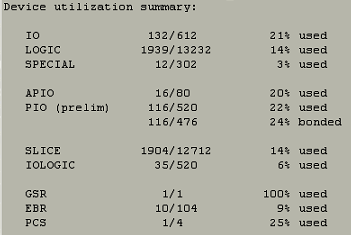
Right now, the current setup on Lattice SCM utilizes the following amount of resources:
Development status:
The Tri-Speed MAC is implemented and works correctly with the test setup on all layers: Ethernet, IP and UDP. All packets sent by HUB are received by PC and correctly recognized as UDP packets. Tri-Speed MAC license after upgrade from trial, works now for unlimited amount of time without interruption.Future steps:
- Measure the speed of transmision
- Add output vector ports to the Packet Transmitter entity with statistics of outgoing packets
- Add support for Jumbo packets
- Examine the scenario when data is sent from TRB to the hub via optical fibre in 8/10 mode (right now the data from TRB is transmitted to the hub using addon connector or randomly generated on hub) and then sent using GbE
- Combine with TRBNet - Migrate to the HUB2 with Lattice ECP2M -- 06 May 2009
| I | Attachment | Action | Size | Date | Who | Comment |
|---|---|---|---|---|---|---|
| |
alg.png | manage | 54 K | 2009-01-15 - 23:41 | GrzegorzKorcyl | alg |
| |
conf2.png | manage | 13 K | 2008-10-18 - 14:22 | GrzegorzKorcyl | test setup |
| |
internal.png | manage | 77 K | 2009-05-05 - 22:59 | GrzegorzKorcyl | internal |
| |
overall.png | manage | 10 K | 2009-05-05 - 23:03 | GrzegorzKorcyl | overall |
| |
packet.png | manage | 28 K | 2009-05-06 - 02:37 | GrzegorzKorcyl | packet structure |
| |
resources.png | manage | 28 K | 2009-05-06 - 00:44 | GrzegorzKorcyl | resources |
| |
str3.png | manage | 33 K | 2008-10-18 - 14:25 | GrzegorzKorcyl | design |
Edit | Attach | Print version | History: r9 < r8 < r7 < r6 | Backlinks | View wiki text | Edit wiki text | More topic actions
Topic revision: r9 - 2009-12-31, JanMichel
Copyright © by the contributing authors. All material on this collaboration platform is the property of the contributing authors.
Ideas, requests, problems regarding Foswiki Send feedback | Imprint | Privacy Policy (in German)
Ideas, requests, problems regarding Foswiki Send feedback | Imprint | Privacy Policy (in German)


