--
AttilioTarantola - 03 May 2009
Here follows the new data structure for MDC readout(OEPB).
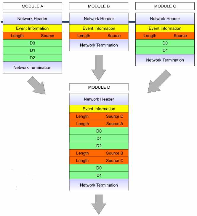
In the following picture (taken from Jan's talk, IKF Seminar 30.04.09), 3 OEPB generate data. These data are then combined in the HUB module (MDC optical addon).
In each OEPB block the
Network Header,
Event Information,
Length-Source
and
Network Termination are generated by the TRBnet entity.
D0,
D1, ..
Dn are generated by the readout entity.
* data structure example:
 Structure of OEP header ?!
| 31 |
30 |
29 |
28 |
27 |
26 |
25 |
24 |
23 |
22 |
21 |
20 |
19 |
18 |
17 |
16 |
15 |
14 |
13 |
12 |
11 |
10 |
9 |
8 |
7 |
6 |
5 |
4 |
3 |
2 |
1 |
0 |
| Length |
Source |
We should seperate this two informations into two 32 bit datawords, and use one full dataword for the source identification. Se my note in
Network addresses for OEP's.
Here an example of 32 bit Normal-Dataword (
D0).
| 31 |
30 |
29 |
28 |
27 |
26 |
25 |
24 |
23 |
22 |
21 |
20 |
19 |
18 |
17 |
16 |
15 |
14 |
13 |
12 |
11 |
10 |
9 |
8 |
7 |
6 |
5 |
4 |
3 |
2 |
1 |
0 |
| Data Type |
TDC Number (1..12) |
TDC Channel#(0-7) |
Data (Hit1-11bit) |
Data (Hit0-11bit) |
In case of 3 datawords per channel or in case of errors which must be transported with the event (i.e. token not retrieved, event broken, errors in the voltages measurement..) an additional Special-Dataword is generated.
Here an example of 32 bit Special-Dataword:
| 31 |
30 |
29 |
28 |
27 |
26 |
25 |
24 |
23 |
22 |
21 |
20 |
19 |
18 |
17 |
16 |
15 |
14 |
13 |
12 |
11 |
10 |
9 |
8 |
7 |
6 |
5 |
4 |
3 |
2 |
1 |
0 |
| Data Type |
TDC number (1..12) |
TDC Channel#(0-7) |
Special-Data_1 (11bit) |
Special-Data_0 (11bit) |
Data Type distinguishes between Normal-Dataword and Special-Datawords.
| Data Type |
Meaning |
Comments |
| "001" |
Normal dataword |
|
| "010" |
Special-dataword |
reserved for 3rd hit |
| "011" |
Special-dataword |
reserved for token not retrieved |
| "100" |
Special-dataword |
two hits in one dataword and error flag(TDC nr/ch missmatch) |
| "101" |
Special-dataword |
single hit (0) |
| "110" |
Calibration-dataword |
|
| "111" |
Calibration-dataword |
error in dataword number |
--
JoernWuestenfeld - 03 Jul 2009
Not so new suggestion by BurkhardKolb
We have two compression modes for the data:
- compressed data - 2 hits in one 32 bit data word
- uncompressed data - 1 hit in one 32 bit data word - DEBUG / noise mode
- These two modes are set for the whole mother board and trigger type and are identified by bit 31.
- In compressed mode all single hit data words are just discarded - so only good data are transmitted.
- In order to see the real noise behaviour of a MOB the mode has to be switched to uncompressed mode.
With this the data type word has only the following values:
| Data Type |
Meaning |
Comments |
| "000" |
Normal compressed data |
|
| "001" |
compressed calibration-dataword |
|
| "010" |
Normal compressed data with ERROR |
reserved for token not retrieved |
| "011" |
compressed calibration-dataword with ERROR |
reserved for token not retrieved |
| "100" |
single-dataword |
one hit in one dataword and hit number in bit 11 |
| "101" |
single calibration |
one hit in one dataword and hit number in bit 11 |
| "110" |
single-dataword with ERROR |
reserved for token not retrieved |
| "111" |
single calibration with ERROR |
reserved for token not retrieved |
So with this the
data type has three bits with a fixed meaning:
- bit 31 if 1 signifies uncompressed data
- bit 30 if 1 signifies ERROR data
- bit 29 if 1 signifies calibration data
--
BurkhardKolb - 03 Jul 2009
Data Structure documentation
 Structure of OEP header ?!
 Structure of OEP header ?!


