You are here: Foswiki>DaqSlowControl Web>OutdatedPages>DaqNetwork>NewTriggerBusConcept>NewTriggerBusMedia (2009-12-31, JanMichel)Edit Attach
New Trigger Bus Media
General IO interface
To make the DaqNetwork independent from any media, a standard IO interface is proposed. The interface follows the principle, that data words are never pushed into the next stage, but always offered and read be the next stage. In detail, the interface should look like:| Line | Decription |
|---|---|
| INT_DATAREADY_OUT | Data word is reconstructed and ready to be read out by the internal logic |
| INT_DATA_OUT[0...55] | Data word |
| INT_READ_IN | Internal logic is reading from the FIFO |
| INT_ERROR_OUT[0..2] | Status bits |
| INT_DATAREADY_IN | Data word is offered by the internal logic or FIFO |
| INT_DATA_IN[0...55] | Data word |
| INT_READ_OUT | Media interface reads a word |
| Bits | Description |
|---|---|
| 000 | Data word OK |
| 001 | Transmission error from the 8B/10B encoding |
| 010 | Transmission error, reconstructed by additional bit |
| 011 | Fatal error, not recoverable |
| 100 | Media not connected |
Slices
To avoid the big register logic of all entities which are using really big buses, the generic "SLICES" should be used.- SLICES=0: Do not use slices, only the big bus
- SLICES>0: Scramble the bus into several slices
Optical Link
The use of an optical links has many advantages:- No charge flow
- Long cable connections (1km!)
- Fast
- Standard technologie (SFP), many vendors
SCSI cable and trb add-on lvds links.
A standard SCSI cable is used for the connection of the AcromagModule. From the 32 IO lines, 16 lines are used for each direction.| Line(s) | Signal |
|---|---|
| 1-13 | Data0-12 |
| 14 | CLK |
| 15 | carrier |
| 16 | Parity |
Additional Media?
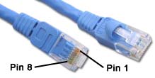
* RJ45: Advantage: 4 twisted pair lines, off-the-shelf cables
Two pairs can be used for downstream (to the endpoints), and 2 for upstream (to the master). This allows to use always one line for clock (if needed) and one for data. LVDS signals should be used, the clock frequency should be choosen that 100m cables could be used.
| Signal | Pin | Color of Line |
|---|---|---|
| UpCLK+ | 1 | white to green |
| UpCLK- | 2 | green |
| UpDATA+ | 3 | white to orange |
| DownCLK+ | 4 | blue |
| DownCLK- | 5 | white to blue |
| UpDATA- | 6 | orange |
| DownDATA+ | 7 | white to brown |
| DownDATA- | 8 | brown |
Edit | Attach | Print version | History: r11 < r10 < r9 < r8 | Backlinks | View wiki text | Edit wiki text | More topic actions
Topic revision: r11 - 2009-12-31, JanMichel
Copyright © by the contributing authors. All material on this collaboration platform is the property of the contributing authors.
Ideas, requests, problems regarding Foswiki Send feedback | Imprint | Privacy Policy (in German)
Ideas, requests, problems regarding Foswiki Send feedback | Imprint | Privacy Policy (in German)
