You are here: Foswiki>DaqSlowControl Web>OutdatedPages>DaqNetwork>TrbNetUsersGuide>TrbNetIPUChannel (2009-05-28, JanMichel)Edit Attach
IPU Data Channel
Data Format
The request to start readout of the data of a specific event is the same as the trigger information delivered on the LVL1 trigger channel - a single TRM packet aka a short transfer: Positions in the network packet are as follows:| Bits | Content |
|---|---|
| 47 - 40 | Additional Information |
| 39 - 32 | Random Data |
| 31 - 16 | 16 bit counter |
| 3 - 0 | Type |
| Word | 15-12 | 11-8 | 7-4 | 3-0 |
|---|---|---|---|---|
| F0 | reserved (CRC) | |||
| F1 | add. information | random code | ||
| F2 | trigger number | |||
| F3 | 0 | seq. no. | type | |
Application Interface
The ipudata-Entity provides an interface to the internal logic to handle all readout requests.| Name | Width | Description |
|---|---|---|
| IPU_TRG_NUMBER_OUT | 16 | Number of the Event to be read out |
| IPU_READOUT_OUT | 1 | data on trb_number is valid during high. Is raised after request is received and reset after readout_finished |
| IPU_DATA_IN | 32 | Data input for event data |
| IPU_DATAREADY_IN | 1 | Datavalid strobe for data_in (offered data is accepted, when read is high in the same clock cycle) |
| IPU_READ_OUT | 1 | Interface is able to accept data |
| IPU_READOUT_FINISHED_IN | 1 | End of transfer by application |
| IPU_LENGTH_IN | 16 | The length of the upcoming data transfer. |
| IPU_ERROR_PATTERN_IN | 32 | Errorbits generated by application. |
- The required format for the sent data stream is described in TrbNetStreamedEventBuilding.
- The trigger random code is transfered with the request packet, but is not offered to the application - otherwise its function as additional security is lost. All entities despite the application are then able to check the code, but the application is forced to save the code as a proof of authenticity.
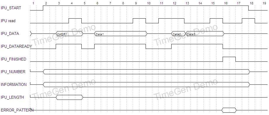
- The read signal will be low for one clock cycle after each dataready due to the conversion from 32 to 16 bit word size.
- Length must be valid during the first dataready signal, error pattern must be valid while readout_finished is high
- Readout of an Event containing three data words on an IPU channel endpoint:

| I | Attachment | Action | Size | Date | Who | Comment |
|---|---|---|---|---|---|---|
| |
ipu_timing_diagram.png | manage | 20 K | 2009-05-28 - 15:17 | JanMichel | Readout of an Event containing three data words on an IPU channel endpoint |
Edit | Attach | Print version | History: r4 < r3 < r2 < r1 | Backlinks | View wiki text | Edit wiki text | More topic actions
Topic revision: r4 - 2009-05-28, JanMichel
Copyright © by the contributing authors. All material on this collaboration platform is the property of the contributing authors.
Ideas, requests, problems regarding Foswiki Send feedback | Imprint | Privacy Policy (in German)
Ideas, requests, problems regarding Foswiki Send feedback | Imprint | Privacy Policy (in German)


