You are here: Foswiki>Homepages Web>CreateHomepageTopic>HomepageBjoernSpruck>PionHodoBjoernSpruck>PionHodoTesting (2007-07-27, BjoernSpruck)Edit Attach
This is only important for setup. During beamtime it would be a bit late.
Example 1:
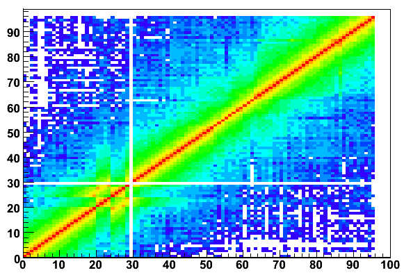
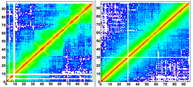
Plotted "crosstalk" in one detector. it is visible, that channel 20-23 is swapped with 24-28. Channel 29 is missing completly, channel 86 seems a bit noisy.
Example 2:
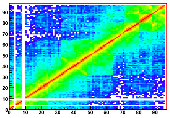
Plotted "crosstalk" in the other detector.
Clearly visible the swapped 8 channels at channel 80-96. The square-like structure indicates too low treshold in (at least) one of the LEDs Another explanaition would be that one PMTs sees some light.
Example 3:
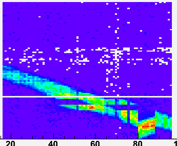
Here the teh correlation between two hodoscopes is plotted. Its immedeatly visible, that several things are wrong here: On detector which is plotted on the y axis, two 4 channel blocks are swapped (see Example 1). On the X axis, the last two 8 chn blocks are swapped, and in one block the cable is plugged in the wrong way (flatribboncable). This is also visible in the width for this signal, because the TDC sees inverted signals for these channels..
Example 4:
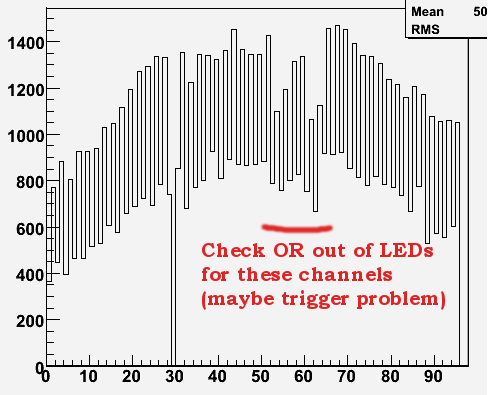
Thsi is the profile for one detector, taken with a Sr90 source. the comb-like structure comes from the geometrical overlap of the fibers. The 16 channels in the middle, which a have a significant lower intensity, are not triggered correctly. The OR out of the LED was not working correctly.
Testing the cabeling:
Example 1:
Plotted "crosstalk" in one detector. it is visible, that channel 20-23 is swapped with 24-28. Channel 29 is missing completly, channel 86 seems a bit noisy.

Example 2:
Plotted "crosstalk" in the other detector.
Clearly visible the swapped 8 channels at channel 80-96. The square-like structure indicates too low treshold in (at least) one of the LEDs Another explanaition would be that one PMTs sees some light.

Example 3:
Here the teh correlation between two hodoscopes is plotted. Its immedeatly visible, that several things are wrong here: On detector which is plotted on the y axis, two 4 channel blocks are swapped (see Example 1). On the X axis, the last two 8 chn blocks are swapped, and in one block the cable is plugged in the wrong way (flatribboncable). This is also visible in the width for this signal, because the TDC sees inverted signals for these channels..

Example 4:
Thsi is the profile for one detector, taken with a Sr90 source. the comb-like structure comes from the geometrical overlap of the fibers. The 16 channels in the middle, which a have a significant lower intensity, are not triggered correctly. The OR out of the LED was not working correctly.

Example 5:
Here all the cables are fixed (except the missing channels, noise, usw).
Example 6:
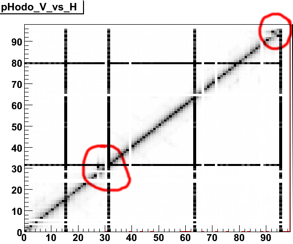
- Left-right correlation with some swapped channels:
clearly visible are some channels which have been swapped (most likely) in the cable connectors or on the LED board. Do not mind the missing channels and the channels which have always fired. The later ones are time reference channels.
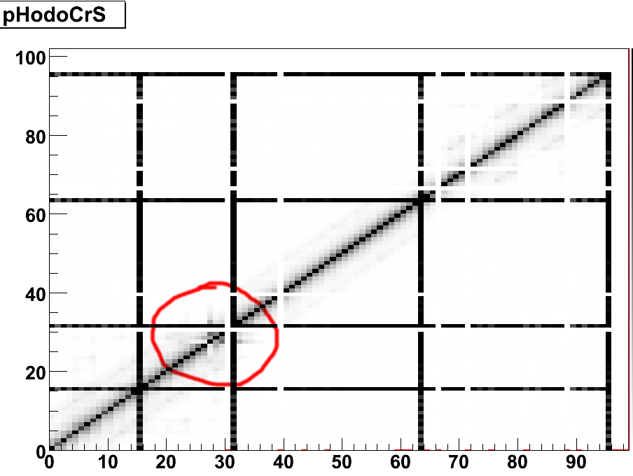
- Corresponding picture for one side crosstalk:
swapped cables one one side
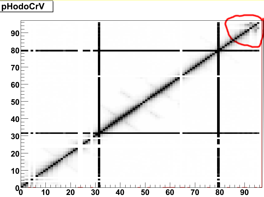
- Corresponding picture for other side crosstalk:
swapped cables one the other side of the detector
| I | Attachment | Action | Size | Date | Who | Comment |
|---|---|---|---|---|---|---|
| |
CT_S_swap.png | manage | 30 K | 2007-07-27 - 09:46 | BjoernSpruck | corresponding picture for one side crosstalk |
| |
CT_V_swap.png | manage | 28 K | 2007-07-27 - 09:47 | BjoernSpruck | corresponding picture for other side crosstalk |
| |
C_swap.png | manage | 26 K | 2007-07-27 - 09:45 | BjoernSpruck | Left-right correlation with some swapped channels |
| |
rpc_test_1vs2.png | manage | 5 K | 2006-03-01 - 15:49 | BjoernSpruck | Example 2 |
| |
rpc_test_cr.png | manage | 27 K | 2006-03-01 - 16:02 | BjoernSpruck | Example 5 |
| |
rpc_test_h_profile.png | manage | 16 K | 2006-03-01 - 15:50 | BjoernSpruck | Example 3 |
| |
rpc_test_hcr.png | manage | 16 K | 2006-03-01 - 15:44 | BjoernSpruck | miscabled |
| |
rpc_test_vcr.png | manage | 17 K | 2006-03-01 - 15:51 | BjoernSpruck | Example 4 |
Edit | Attach | Print version | History: r3 < r2 < r1 | Backlinks | View wiki text | Edit wiki text | More topic actions
Topic revision: r3 - 2007-07-27, BjoernSpruck
Copyright © by the contributing authors. All material on this collaboration platform is the property of the contributing authors.
Ideas, requests, problems regarding Foswiki Send feedback | Imprint | Privacy Policy (in German)
Ideas, requests, problems regarding Foswiki Send feedback | Imprint | Privacy Policy (in German)


